

What are the CAD shortcut key commands?

CAD is a computer-aided design software widely used in mechanical design, architectural design, electrical design and other fields. Its use can greatly improve design efficiency and accuracy. When using CAD software, mastering some shortcut key commands can help us complete design tasks more efficiently. The following is a list of CAD shortcut key commands.
1. Basic operation categories
(1) Z: Undo the previous operation.
(2) U: Resume the operation that was undone in the previous step.
(3) E: Switch to entity editing mode.
(4) P: Switch to brush mode.
(5) L: Switch to straight line drawing mode.
(6) C: Switch to circle drawing mode.
(7) R: Switch to rectangular drawing mode.
(8) M: Move the selected object.
(9) S: Scale the selected object.
(10) A: Rotate the selected object.
(11) B: Mirror the selected object.
(12) F: Fill the selected object.
(13) H: Hide the selected object.
(14) J: Show hidden objects.
2. Drawing class
(1) Ctrl N: Create a new drawing file.
(2) Ctrl O: Open an existing drawing file.
(3) Ctrl S: Save the current drawing file.
(4) Ctrl P: Print the current drawing file.
(5) Ctrl Z: Undo the previous operation.
(6) Ctrl Y: Resume the undone operation in the previous step.
(7) Ctrl C: Copy the selected object.
(8) Ctrl V: Paste the copied object.
(9) Ctrl X: Cut the selected object.
(10) Ctrl A: Select all objects.
(11) Ctrl F: Find objects.
(12) Ctrl G: Group selected objects.
(13) Ctrl Shift G: Ungroup selected objects.
(14) Ctrl Shift C: Copy the properties of the object.
(15) Ctrl Shift V: Paste the properties of the object.
(16) Ctrl Shift X: Cut the properties of the object.
(17) Ctrl Shift A: Select all similar objects.
(18) Ctrl Shift F: Find and replace objects.
3. Editing class
(1) F2: Open the command line window.
(2) F3: Open the object property manager.
(3) F4: Open the toolbox.
(4) F5: Open the property editor.
(5) F6: Open the layer manager.
(6) F7: Open the viewport controller.
(7) F8: Turn on grid display.
(8) F9: Turn on the coordinate axis display.
(9) F10: Open preferences.
(10) F11: Open object snap settings.
(11) F12: Open command settings.
(12) Ctrl 1: Open the property manager.
(13) Ctrl 2: Open the Design Center.
(14) Ctrl 3: Open the layer manager.
(15) Ctrl 4: Open the style manager.
(16) Ctrl 5: Open the block editor.
(17) Ctrl 6: Open the image manager.
(18) Ctrl 7: Open the viewport manager.
(19) Ctrl 8: Open the multi-line text editor.
(20) Ctrl 9: Open the command line window.
4. Selection class
(1) Shift space: switch to selection mode.
(2) Ctrl Shift A: Select all similar objects.
(3) Ctrl Shift B: Select all objects in the frame selection area.
(4) Ctrl Shift C: Copy the properties of the object.
(5) Ctrl Shift V: Paste the properties of the object.
(6) Ctrl Shift X: Cut the properties of the object.
(7) Ctrl Shift Z: Redo the undone operation in the previous step.
(8) Ctrl Shift Y: Redo the operation that was restored in the previous step.
(9) Ctrl Shift F: Find and replace objects.
(10) Alt Space: Display the object menu.
(11) Alt F8: Open the macro manager.
(12) Alt F10: Open the options dialog box.
(13) Alt F11: Open the VBA editor.
5. View class
(1) Ctrl 0: Switch to model space.
(2) Ctrl 1: Switch to portrait layout.
(3) Ctrl 2: Switch to landscape layout.
(4) Ctrl 3: Open the layer manager.
(5) Ctrl 4: Open the style manager.
(6) Ctrl 5: Open the block editor.
(7) Ctrl 6: Open the image manager.
(8) Ctrl 7: Open the viewport manager.
(9) Ctrl 8: Open the multi-line text editor.
(10) Ctrl 9: Open the command line window.
(11) Ctrl Shift W: Close the current layout.
(12) Ctrl Shift T: Open a new layout tab.
(13) Ctrl Shift S: Save the current viewport settings.
(14) Ctrl Shift R: Restore the last saved viewport settings.
(15) Ctrl Shift F: Full screen display.
(16) Ctrl Shift P: Open print settings.
(17) Ctrl Shift I: Open image settings.
(18) Ctrl Shift H: Open the help document.
The above is a complete list of CAD shortcut key commands, I hope it will be helpful to everyone. When using CAD software, mastering these shortcut key commands can greatly improve work efficiency and allow us to complete design tasks more efficiently.
The above is the detailed content of What are the CAD shortcut key commands?. For more information, please follow other related articles on the PHP Chinese website!

Hot AI Tools

Undresser.AI Undress
AI-powered app for creating realistic nude photos

AI Clothes Remover
Online AI tool for removing clothes from photos.

Undress AI Tool
Undress images for free

Clothoff.io
AI clothes remover

Video Face Swap
Swap faces in any video effortlessly with our completely free AI face swap tool!

Hot Article
Hot Tools

Notepad++7.3.1
Easy-to-use and free code editor

SublimeText3 Chinese version
Chinese version, very easy to use

Zend Studio 13.0.1
Powerful PHP integrated development environment

Dreamweaver CS6
Visual web development tools

SublimeText3 Mac version
God-level code editing software (SublimeText3)
Hot Topics


 binance official website URL Binance official website entrance latest genuine entrance
Dec 16, 2024 pm 06:15 PM
binance official website URL Binance official website entrance latest genuine entrance
Dec 16, 2024 pm 06:15 PM
This article focuses on the latest genuine entrances to Binance’s official website, including Binance Global’s official website, the US official website and the Academy’s official website. In addition, the article also provides detailed access steps, including using a trusted device, entering the correct URL, double-checking the website interface, verifying the website certificate, contacting customer support, etc., to ensure safe and reliable access to the Binance platform.
 How to use the cad stretch command-how to use the cad stretch command
Mar 06, 2024 pm 02:31 PM
How to use the cad stretch command-how to use the cad stretch command
Mar 06, 2024 pm 02:31 PM
Many novice friends still don’t know how to use the cad stretch command, so the editor below will bring you how to use the cad stretch command. Friends in need can quickly take a look. Step 1: Open the CAD software. For example, you want to stretch the triangle below, as shown in the picture below. Step 2: Enter the s shortcut key command in the command bar below and press Enter, as shown in the figure below. Step 3: Then select the object from right to left and press Enter (Note: It can neither be lower than the lower boundary nor exceed the upper vertex, and must be between the parts that need to be stretched.), as shown in the figure below. Step 4: Then specify the base point according to the prompts, as shown in the figure below. Step 5: Stretch to the specified position according to the drawing requirements and click to complete the stretching, as shown in the figure below. The above is the cad stretching instructions that the editor brings to you.
 How to measure the area of graphics in CAD Viewer. How to measure the area of graphics in CAD Viewer.
Mar 13, 2024 pm 01:43 PM
How to measure the area of graphics in CAD Viewer. How to measure the area of graphics in CAD Viewer.
Mar 13, 2024 pm 01:43 PM
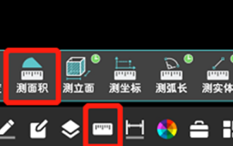
How to measure the area of graphics in CAD Viewer? CAD Viewer is a very easy-to-use software for viewing engineering drawings. This software has many functions, and drawings in various formats can be opened and viewed. If when we look at the drawings, we find that the area measurement of some graphics is wrong or that some graphics forget to measure the area, we can use this software to measure the area of the graphics. So how to measure the area of graphics? Below, the editor of this site has compiled a CAD drawing king's steps to measure the area of graphics for your reference. Steps for measuring the graphic area in CAD Viewer 1. First, open the drawing file in CAD Viewer APP, take the drawing with arc graphics as an example, and measure the area of the graphic. 2. After opening the drawing, go to the bottom of the software interface
 How to use CAD continuous annotation - CAD continuous annotation usage tutorial
Mar 05, 2024 pm 05:46 PM
How to use CAD continuous annotation - CAD continuous annotation usage tutorial
Mar 05, 2024 pm 05:46 PM
Recently, many friends have asked the editor how to use CAD continuous annotation. Next, let us learn the tutorial on how to use CAD continuous annotation. I hope it can help everyone. Step 1: Open CAD, take a multi-line segment as an example, as shown in the figure. Step 2: Click Label and select the desired label type, as shown in the figure. Step 3: Label the first segment of the multi-line segment, as shown in the figure. Step 4: After the first labeling is completed, enter the shortcut command "dco" for continuous labeling, as shown in the figure. Step 5: Click on the endpoints of the line segments that need to be marked in order to mark continuously, as shown in the figure. Step 6: Finally, it is completed, as shown in the picture. The above is the entire content of how to use CAD continuous annotation brought to you by the editor. I hope it can be helpful to everyone.
 Apple Watch Series 10: Leaked CAD images reveal larger display than Apple Watch Ultra but minimal design changes
Jun 28, 2024 am 02:13 AM
Apple Watch Series 10: Leaked CAD images reveal larger display than Apple Watch Ultra but minimal design changes
Jun 28, 2024 am 02:13 AM
Apple likely remains a few months off from unveiling its next batch of smartwatches. Given the timing of its Watch Series 9 and Watch Ultra 2 (curr. $646.94 - refurbished on Amazon) announcements, it seems that Apple will hold out until September bef
 Laravel Redis connection sharing: Why does the select method affect other connections?
Apr 01, 2025 am 07:45 AM
Laravel Redis connection sharing: Why does the select method affect other connections?
Apr 01, 2025 am 07:45 AM
The impact of sharing of Redis connections in Laravel framework and select methods When using Laravel framework and Redis, developers may encounter a problem: through configuration...
 Vue and Element-UI cascaded drop-down box props pass value
Apr 07, 2025 pm 07:36 PM
Vue and Element-UI cascaded drop-down box props pass value
Apr 07, 2025 pm 07:36 PM
The data structure must be clearly defined when the Vue and Element-UI cascaded drop-down boxes pass the props, and the direct assignment of static data is supported. If data is dynamically obtained, it is recommended to assign values within the life cycle hook and handle asynchronous situations. For non-standard data structures, defaultProps or convert data formats need to be modified. Keep the code simple and easy to understand with meaningful variable names and comments. To optimize performance, virtual scrolling or lazy loading techniques can be used.
 How to convert PDF to CAD
Mar 19, 2024 pm 06:10 PM
How to convert PDF to CAD
Mar 19, 2024 pm 06:10 PM
As an excellent software related to industry such as construction, CAD is often indispensable when performing related professional work. It is precisely because of CAD that work efficiency has been greatly improved. As we all know, its functions are also rich and diverse, and one of the more outstanding functions is PDF to CAD. In many cases, when merchants cannot forward CAD in time and can only forward PDF, this function is needed. So let me tell you how to operate it specifically. 1. Open the CAD software and find Insert. Find "PDF Underlay" in Insert. 2. Next, find the PDF image you want to convert in "PDF Underlay" and open it. 3. Modify the ratio to 25.4, keep other things unchanged, and click OK. 4.