

SQL server quick basic database application system

This article brings you relevant knowledge about SQL server, which mainly introduces related issues about database basics, including an introduction to simple database application systems and database design. The following is Let's take a look, hope it helps everyone.

SQL Tutorial"
Database Concept
- Database
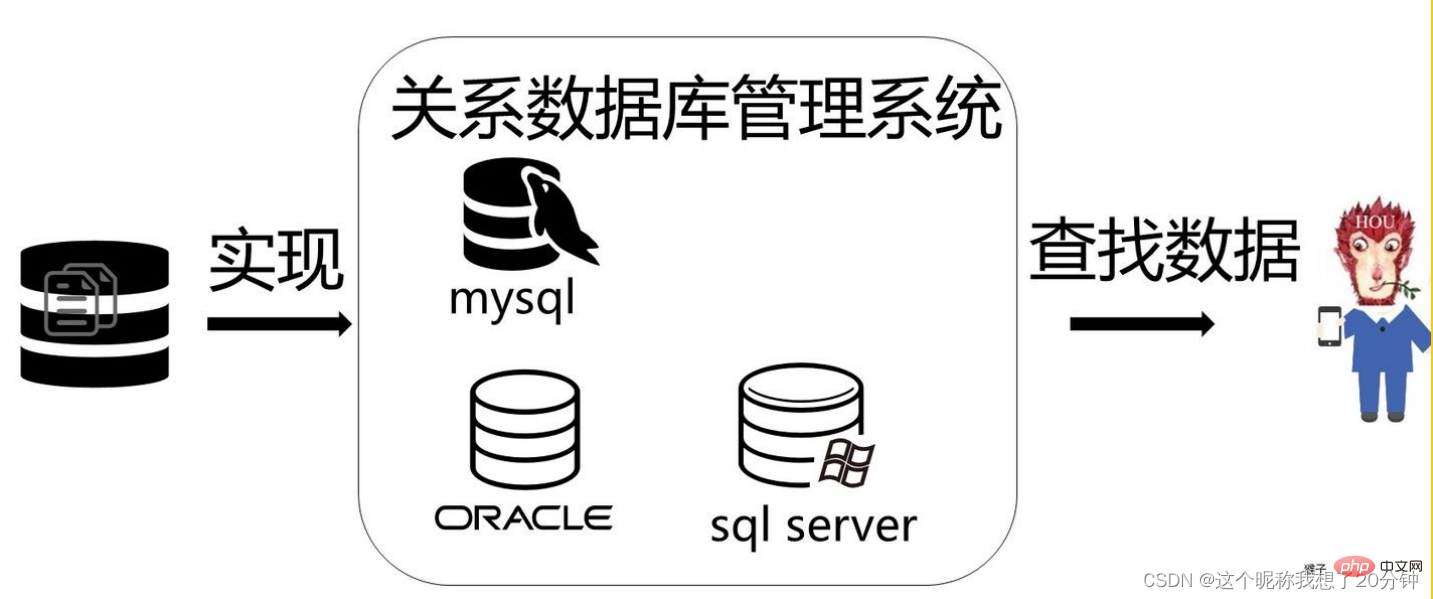
Data organized according to a certain model is called a database (DataBase, DB). The database is the core and foundation of
transaction processing, information management and other application systems. - DataBase Management System (DBMS)
manages databases and other systems. It organizes a large amount of data according to a certain data model and provides
storage, The functions of maintaining and retrieving data enable the application system to obtain the required information from the database conveniently,
timely and accurately in a unified manner.
How does the database organize (store) data?
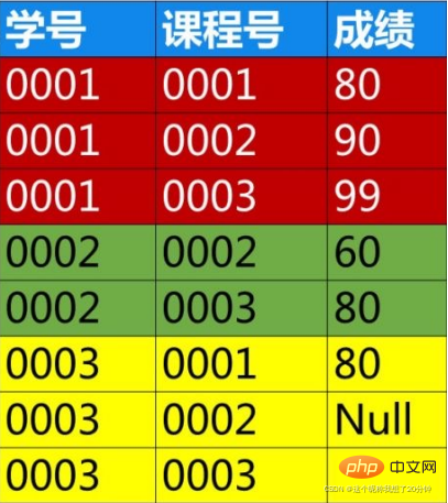
During project development, a suitable database management system must be selected to organize the data according to a certain data model, conduct unified management of the data, and provide consistent access means for applications that need to use the data. . Data models mainly include relational models, hierarchical models, and network models. Currently, the relational model is more commonly used. The relational model organizes data in the database in the form of two-dimensional tables (relational tables). For example: Table 1.1 describes the student data in the student book lending system at a certain moment.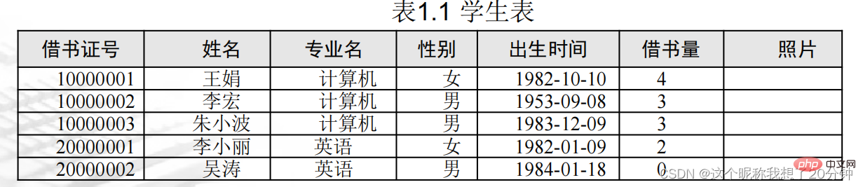
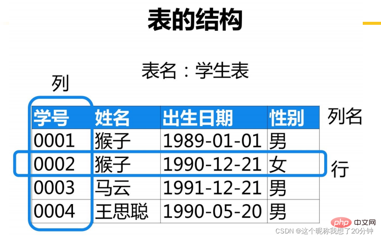
A row in the table is called For records, a column is called a field, and the title is the field name.
Relational table structure representation: Relational table name (field name 1, field name 2...field
- name n)
1.2 Database designRelationship between tables: Student tableCode: The value of a field or the smallest combination of fields can uniquely identify its corresponding record. There can be multiple codes in a
- table. Generally, one code is designated as the main code, which is represented by an underline
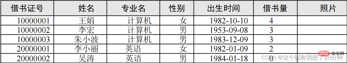
in the relationship table. For example, student table xs (library card number, name, gender, date of birth, major, number of borrowed books
).
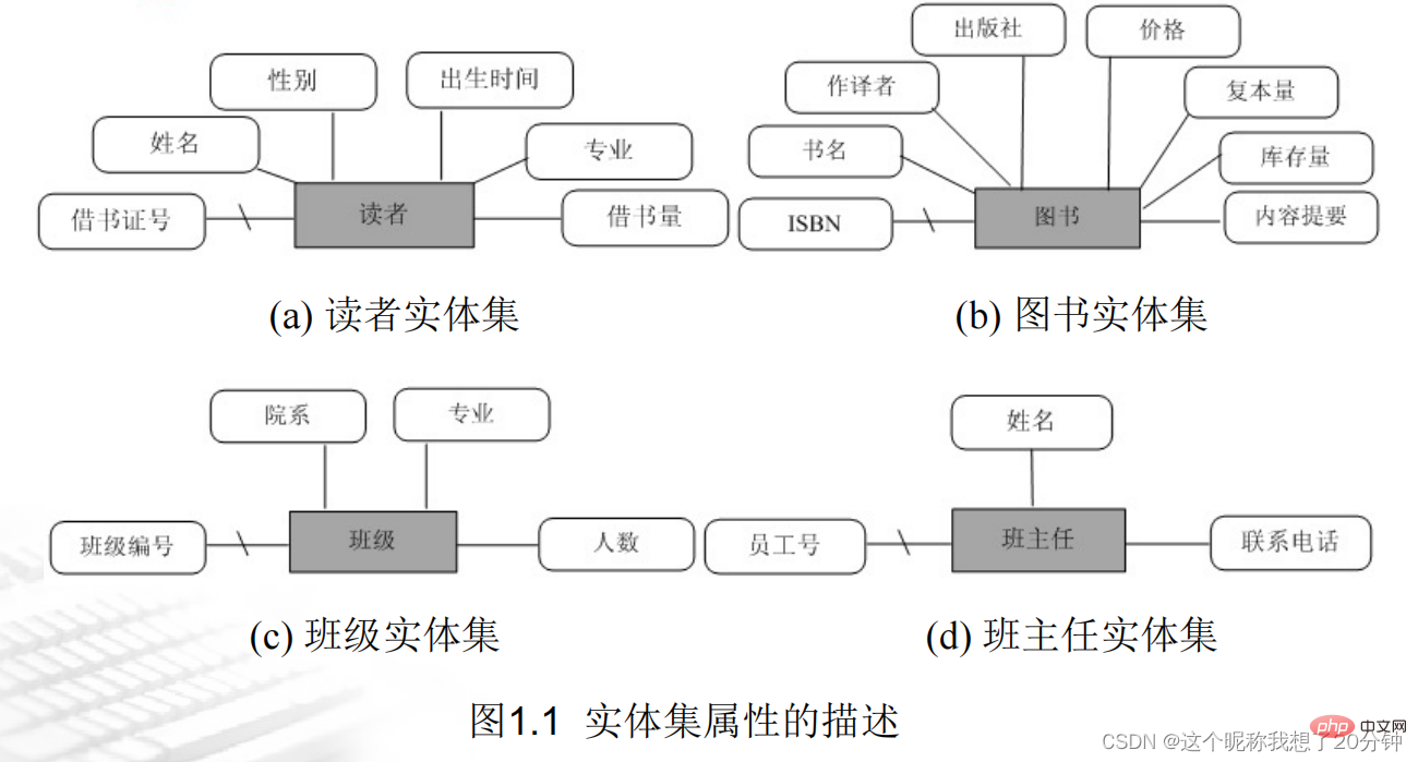
(1) Entity set representation In the E-R diagram, rectangles are used to represent entity sets, ellipses are used to represent attributes, and diamonds are used to represent relationships. Use a line segment to connect the entity set and attributes. When an attribute or attribute combination is designated as the main code, mark a slash on the line connecting the entity set and attributes.
(2) Various relationships exist between entity sets
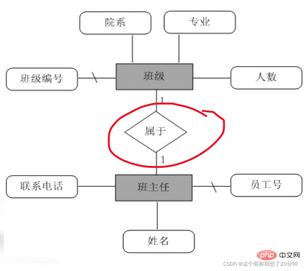
1. One-to-one relationship (1:1) An entity in A is associated with at most one entity in B, and an entity in B is associated with at most one entity in A. For example, the relationship between the two entity sets "class" and "class teacher" is a one-to-one relationship, because a class has only one class teacher, and conversely, a class teacher only belongs to one class. The E-R model of the two entity sets "class" and "class teacher" is shown in Figure 1.2.
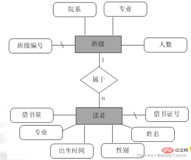
2. One-to-many relationship (1:n) An entity in A can be associated with multiple entities in B, and an entity in B is associated with at most one entity in A. For example, the relationship between the two entity sets "class" and "student" (reader) is a one-to-many relationship, because a class can have several students, and conversely, a student can only belong to one class. The E-R model of the two entity sets "class" and "student" is shown in Figure 1.3.
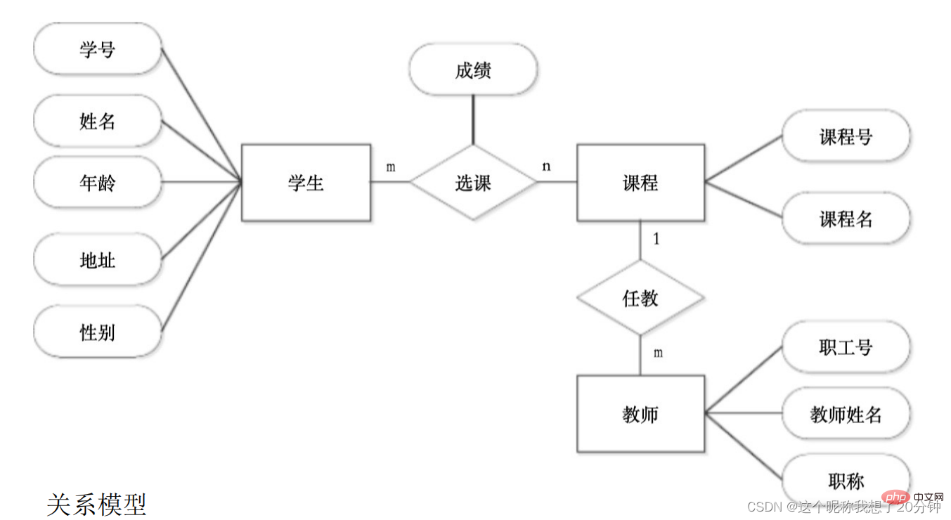
3. Many-to-many relationship (m : n) An entity in A can be associated with multiple entities in B, and an entity in B can also be associated with multiple entities in A. For example, the relationship between the two entity sets "readers" (students) and "books" is a many-to-many relationship, because a reader can borrow multiple books, and conversely, a book with a book number can be borrowed by multiple students. . The E-R model of the two entity sets "reader" and "book" is shown in Figure 1.4.

There are two entities: store and customer. "Store" has attributes: store number, store name, address, phone number, "customer" "There are attributes: customer number, name, address, age, gender. Assume that every time a customer goes to the store to shop, he has a consumption amount and a date. Try to draw an E-R diagram and indicate the attributes and contact types. 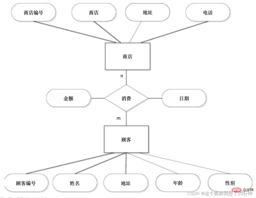
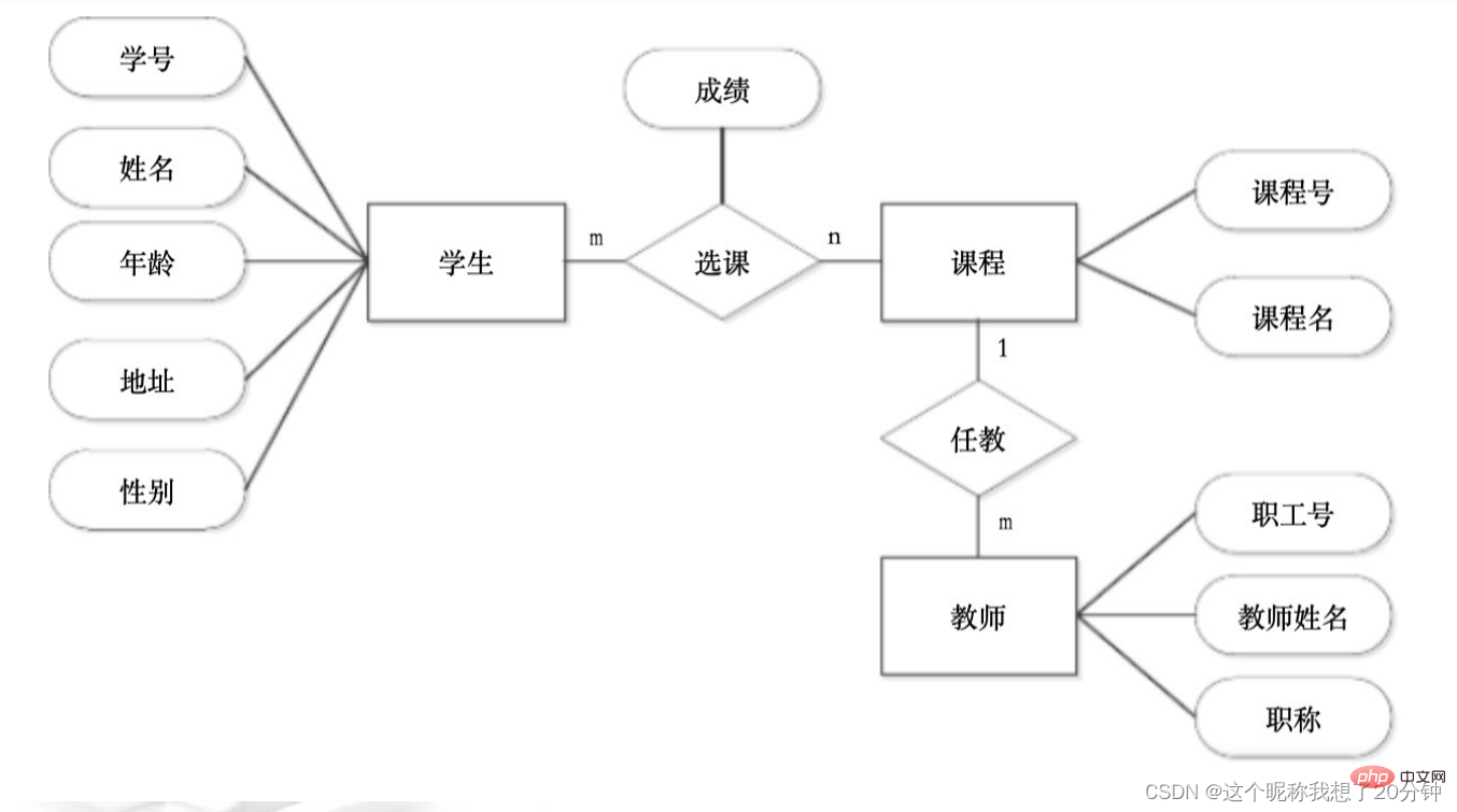
Suppose each student takes several courses, and each student only has one grade for each course, and each teacher only Responsible for teaching one course, and one course is taught by several teachers. "Student" has attributes: student number, name, address, age, and gender. "Teacher" has attributes: employee number, teacher name, and professional title, and "course" has attributes: course number, course name. Try to draw an ER diagram and indicate the attributes and contact types.
1.2.2 Logical data model
The following is a method to obtain the relationship pattern from the E-R diagram based on three connections.
1. (1 : 1) Conversion of the associated E-R diagram to the relationship schema
a. Each entity set corresponds to a relationship schema;
b. For (1 : 1 ) may correspond to a relationship model alone, or may not correspond to a relationship model alone.
(1) A relationship alone corresponds to a relationship model, and the relationship model is composed of the contact attributes and the primary key attributes of each entity set participating in the contact. The primary code can be the primary code of any party in the entity set participating in the contact.
For example, consider the "class (bj)" and "class teacher (bzr)" entity sets described in Figure 1.2 to contact the E-R model through belonging (sy). The following relationship pattern can be designed (the underline indicates that the field is the main code) :
bj (class number, department, major, number of people)
bzr (employee number, name, contact number)
sy (employee number, class number)
(2) Contact does not correspond individually In a relationship schema, the attributes of the relationship and the primary key of one party are added to the relationship schema corresponding to the entity set of the other party.
For example, consider the entity set of "Class (bj)" and "Class Teacher (bzb)" described in Figure 1.2 to contact the E-R model through belonging (sy). The following relationship model can be designed:
bj (class number, department , major, number of people)
bzr (employee number, name, contact number, class number)
or:
bj (class number, department, major, number of people, employee number)
bzr (employee Number, name, contact number)
2. (1: n) Conversion of E-R diagram to relationship schema
ˆ ˆ a. Each entity set corresponds to a relationship schema;
ˆ ˆ b. For (1: n) contact, it can correspond to a separate relationship schema , it does not need to correspond to a
relationship pattern alone.
(1) A relationship alone corresponds to a relationship pattern, and the relationship pattern is composed of the attributes of the association and the primary key attributes of each entity set participating in the association. The primary key at the n end is used as the primary key of the relationship pattern.
For example, considering the E-R model of the "class (bj)" and "student (xs)" entity sets described in Figure 1.3, the following relationship model can be designed:
bj (class number, department, major, number of people)
xs (library card number, name, gender, birth time, major, number of books borrowed)
sy (library card number, class number)
(2) The relationship does not correspond to a separate relationship model, then Add the attributes of the relationship and the primary code at the 1 end to the relationship pattern corresponding to the real
entity set at the n end, and the primary code is still the primary code at the n end.
For example, the E-R model of the "class (bj)" and "reader (xs)" entity sets described in Figure 1.3 can be designed with the following relationship pattern:
bj (class number, department, major, number of people)
xs (library card number, name, gender, date of birth, major, number of books borrowed, class number)
3. Conversion of E-R diagram of (m : n) contact to relationship schema
ˆ ˆ a. Each entity set corresponds to a relationship schema;
ˆ ˆ b. For (m : n) contact, there is a separate relationship schema, which The relationship model includes the attributes of the relationship and the primary key attributes of each entity set participating in the relationship. The primary key of the relationship model is composed of the primary key attributes of each entity set.
For example, the borrowing relationship (jy) between the "reader (xs)" and "book (book)" entity set described in Figure 1.4 can be designed as follows:
xs (library card) Number, name, gender, date of birth, major, number of books borrowed)
book (ISBN, book title, translator, publisher, price, number of copies, inventory, summary)
jy (borrowed Library card number, ISBN, call number, borrowing time)
The main key of the relationship model jy is a
primary key and a relationship composed of the two attributes "library card number" and "ISBN" A pattern can only have one primary code.
Exercise 1: There are two entities: store and customer. "Store" has attributes: store number, store name, address, phone number. "Customer" has attributes: customer Number, name, address, age, gender. Assume that every time a customer goes to the store to shop, he has a consumption amount and a date. Draw an E-R diagram and convert it into a relational model.
 ##
##
: Assume that each student takes several courses, and each student only has one grade for each course, and each teacher only Responsible for teaching one course, and one course is taught by several teachers. "Student" has attributes: student number, name, address, age, and gender. "Teacher" has attributes: employee number, teacher name, and professional title, and "course" has attributes: course number, course name. Try to draw an ER diagram and convert the E-R diagram into a relational model.
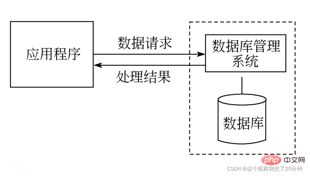
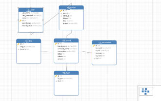
The structure of the database system is described as shown in Figure 1.5.
 1.3.1 Data interface of application system
1. ODBC database interface
ODBC stands for Open DataBase Connectivity. It is an interface standard introduced by Microsoft to implement communication between applications and relational databases. Databases that meet this standard can operate the database through programs written in SQL statements, but only for relational databases. All current relational databases comply with this standard. ODBC is essentially a set of database access APIs (application programming interfaces), consisting of a set of function calls, with the core being SQL statements.
2. ADO database interface
3. ADO.NET Database Interface
The ADO.NET data model is developed from ADO, but it is not just an improvement on ADO, but uses a brand new technology. Mainly reflected in the following aspects:
(1) ADO.NET does not use ActiveX technology, but is a product closely integrated with the .NET framework.
(2) ADO.NET includes full support for the XML standard, which is of great significance for cross-platform data exchange.
(3) ADO.NET can work both in an environment connected to the data source and in an environment disconnected from the data source. In particular, the latter is very suitable for the needs of network applications, because in a network environment, always maintaining a connection with the data source does not meet the requirements of the website. It is not only inefficient and costly, but also often causes problems due to multiple users simultaneously. Conflicts caused by access.
JDBC (Java DataBase Connectivity) is developed by JavaSoft (the original business department of SUN company). It is a class and interface written in Java language for database connection and operation. It can provide unified access to a variety of relational databases. Way. Access to the database through JDBC includes 4 main components: Java application, JDBC driver manager, driver and data source.
Using the JDBC interface to operate the database has the following advantages:
(1) The JDBC API is very similar to ODBC, which is helpful for users to understand;
(2) It frees programmers from complex driver calling commands and functions , and is dedicated to the implementation of application
program functions;
(3) JDBC supports different relational databases, enhancing the portability of the program.
For database applications in network environments, due to the large number of users, the traditional JDBC method is used for database connections. Excessive system resource overhead has become a bottleneck restricting the efficiency of large enterprise-level applications. Database connection pool technology is used to Connection management can greatly improve the efficiency and stability of the system.
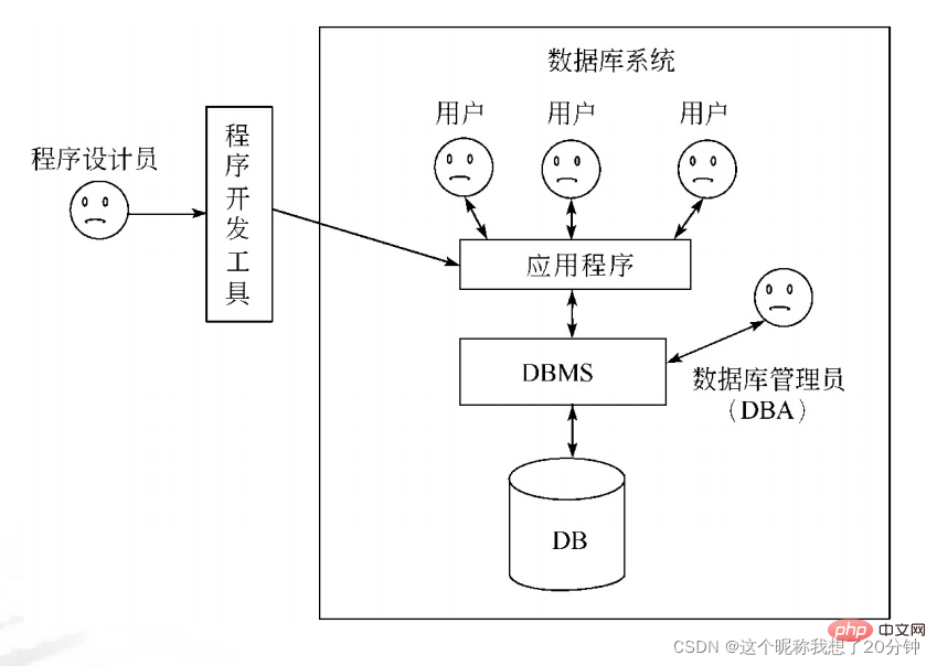
DBMS operates the database through commands and an interface suitable for professionals. For general database application systems, in addition to DBMS, it is also necessary to design an interface suitable for ordinary people to operate the database. At present, the popular tools for developing database interfaces mainly include Visual Basic, Visual C, Visual C#, etc. The relationship between the application, the database, and the database management system is shown in the figure.
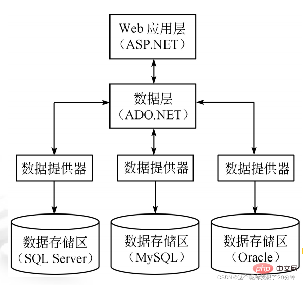
Web-based database applications adopt a three-tier (browser/Web server/database server) model, also known as B/S architecture, as shown in the figure. 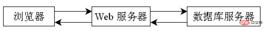
SQL Tutorial"
The above is the detailed content of SQL server quick basic database application system. For more information, please follow other related articles on the PHP Chinese website!

Hot AI Tools

Undresser.AI Undress
AI-powered app for creating realistic nude photos

AI Clothes Remover
Online AI tool for removing clothes from photos.

Undress AI Tool
Undress images for free

Clothoff.io
AI clothes remover

Video Face Swap
Swap faces in any video effortlessly with our completely free AI face swap tool!

Hot Article
Hot Tools

Notepad++7.3.1
Easy-to-use and free code editor

SublimeText3 Chinese version
Chinese version, very easy to use

Zend Studio 13.0.1
Powerful PHP integrated development environment

Dreamweaver CS6
Visual web development tools

SublimeText3 Mac version
God-level code editing software (SublimeText3)
Hot Topics


 What is the difference between HQL and SQL in Hibernate framework?
Apr 17, 2024 pm 02:57 PM
What is the difference between HQL and SQL in Hibernate framework?
Apr 17, 2024 pm 02:57 PM
HQL and SQL are compared in the Hibernate framework: HQL (1. Object-oriented syntax, 2. Database-independent queries, 3. Type safety), while SQL directly operates the database (1. Database-independent standards, 2. Complex executable queries and data manipulation).
 Usage of division operation in Oracle SQL
Mar 10, 2024 pm 03:06 PM
Usage of division operation in Oracle SQL
Mar 10, 2024 pm 03:06 PM
"Usage of Division Operation in OracleSQL" In OracleSQL, division operation is one of the common mathematical operations. During data query and processing, division operations can help us calculate the ratio between fields or derive the logical relationship between specific values. This article will introduce the usage of division operation in OracleSQL and provide specific code examples. 1. Two ways of division operations in OracleSQL In OracleSQL, division operations can be performed in two different ways.
 Comparison and differences of SQL syntax between Oracle and DB2
Mar 11, 2024 pm 12:09 PM
Comparison and differences of SQL syntax between Oracle and DB2
Mar 11, 2024 pm 12:09 PM
Oracle and DB2 are two commonly used relational database management systems, each of which has its own unique SQL syntax and characteristics. This article will compare and differ between the SQL syntax of Oracle and DB2, and provide specific code examples. Database connection In Oracle, use the following statement to connect to the database: CONNECTusername/password@database. In DB2, the statement to connect to the database is as follows: CONNECTTOdataba
 Detailed explanation of the Set tag function in MyBatis dynamic SQL tags
Feb 26, 2024 pm 07:48 PM
Detailed explanation of the Set tag function in MyBatis dynamic SQL tags
Feb 26, 2024 pm 07:48 PM
Interpretation of MyBatis dynamic SQL tags: Detailed explanation of Set tag usage MyBatis is an excellent persistence layer framework. It provides a wealth of dynamic SQL tags and can flexibly construct database operation statements. Among them, the Set tag is used to generate the SET clause in the UPDATE statement, which is very commonly used in update operations. This article will explain in detail the usage of the Set tag in MyBatis and demonstrate its functionality through specific code examples. What is Set tag Set tag is used in MyBati
 What does the identity attribute in SQL mean?
Feb 19, 2024 am 11:24 AM
What does the identity attribute in SQL mean?
Feb 19, 2024 am 11:24 AM
What is Identity in SQL? Specific code examples are needed. In SQL, Identity is a special data type used to generate auto-incrementing numbers. It is often used to uniquely identify each row of data in a table. The Identity column is often used in conjunction with the primary key column to ensure that each record has a unique identifier. This article will detail how to use Identity and some practical code examples. The basic way to use Identity is to use Identit when creating a table.
 How to implement Springboot+Mybatis-plus without using SQL statements to add multiple tables
Jun 02, 2023 am 11:07 AM
How to implement Springboot+Mybatis-plus without using SQL statements to add multiple tables
Jun 02, 2023 am 11:07 AM
When Springboot+Mybatis-plus does not use SQL statements to perform multi-table adding operations, the problems I encountered are decomposed by simulating thinking in the test environment: Create a BrandDTO object with parameters to simulate passing parameters to the background. We all know that it is extremely difficult to perform multi-table operations in Mybatis-plus. If you do not use tools such as Mybatis-plus-join, you can only configure the corresponding Mapper.xml file and configure The smelly and long ResultMap, and then write the corresponding sql statement. Although this method seems cumbersome, it is highly flexible and allows us to
 How to solve the 5120 error in SQL
Mar 06, 2024 pm 04:33 PM
How to solve the 5120 error in SQL
Mar 06, 2024 pm 04:33 PM
Solution: 1. Check whether the logged-in user has sufficient permissions to access or operate the database, and ensure that the user has the correct permissions; 2. Check whether the account of the SQL Server service has permission to access the specified file or folder, and ensure that the account Have sufficient permissions to read and write the file or folder; 3. Check whether the specified database file has been opened or locked by other processes, try to close or release the file, and rerun the query; 4. Try as administrator Run Management Studio as etc.
 How to use SQL statements for data aggregation and statistics in MySQL?
Dec 17, 2023 am 08:41 AM
How to use SQL statements for data aggregation and statistics in MySQL?
Dec 17, 2023 am 08:41 AM
How to use SQL statements for data aggregation and statistics in MySQL? Data aggregation and statistics are very important steps when performing data analysis and statistics. As a powerful relational database management system, MySQL provides a wealth of aggregation and statistical functions, which can easily perform data aggregation and statistical operations. This article will introduce the method of using SQL statements to perform data aggregation and statistics in MySQL, and provide specific code examples. 1. Use the COUNT function for counting. The COUNT function is the most commonly used
