
 Technology peripherals
AI
Design of an ultra-comprehensive system time synchronization solution for the next-generation autonomous driving system
Technology peripherals
AI
Design of an ultra-comprehensive system time synchronization solution for the next-generation autonomous driving system
Design of an ultra-comprehensive system time synchronization solution for the next-generation autonomous driving system

The next generation autonomous driving system needs to use various sensors such as multiple laser radars, multiple millimeter wave radars, and multiple cameras. There is a delay from collecting data to processing and sending it to the domain controller, and there is a delay. The duration is unstable. In order to improve the performance of autonomous driving such as sensor fusion, decision planning and fusion positioning, the autonomous driving advanced domain controller HPC and its associated sensors need to be time synchronized. The actual process is to clearly define the timestamp information of the sensor input data (including the time). Stamping time and accuracy requirements), and also need to define the overall time synchronization plan and synchronization accuracy requirements.
Overview
To explain the principle of clock synchronization clearly, we need to first explain the two types of clock synchronization: data clock and management clock. First of all, the UTC time provided by the combined inertial navigation system is used to provide timing to the time synchronization server through PPS GPRMC. The time synchronization server provides corresponding time information to various sensor data collection hosts through the PTP protocol and the central gateway. HPC needs to implement the time synchronization process between the internal SOC and MCU.

The data plane time between the SOC of the HPC and the MCU is synchronized through the gPTP protocol time, where the SOC is Master; the management plane time between the HPC's SOC and MCU is synchronized through the HPC private protocol. The SOC is the master and synchronized through the Ethernet link.
During the synchronization process between SOC and MCU, the management clock and data clock will be synchronized. The data plane uses the gPTP protocol. Within the time synchronization accuracy requirement of 250 microseconds, the management clock uses a private protocol. Also over Ethernet, the accuracy is 10ms. Its internal management time and data plane time need to be aligned. HPC must ensure the continuity of the data clock and does not allow abnormal jumps. Because abnormal jumps can cause serious data miscommunication and misinterpretation.
Every time the domain controller cold starts, the domain controller will try to communicate with the node that provides the master clock for a certain period of time (this time can be calibrated as needed according to the actual situation) to Perform initial synchronization. If the synchronization is successful, the data clock will use the current management time to synchronize the obtained absolute time; the corresponding driver can be started with it and call the corresponding application software for calculation. If synchronization is unsuccessful, the domain controller will keep trying to synchronize.
HPC and VDC synchronization process
The entire synchronization classification mainly includes the relationship between the central domain controller and gateway, various sensors and actuators synchronization. The absolute time of HPC usually provides a unified time source for all controllers of the vehicle through the central gateway CGW, and outputs the overall synchronization timestamp to all associated controllers (such as body domain controller PDC, vehicle domain controller VDC, cockpit Domain Controller CSC, etc.). In the next-generation autonomous driving system architecture, the vehicle domain controller VDC not only assumes the function of controlling the operation of the vehicle actuator, but also serves as the central gateway CGW, carrying information interaction and protocols between HPC and other domain controllers. Transformation function.
The following figure shows the connection relationship between the automatic driving controller HPC and its associated domain controller.

As mentioned above, VDC can function as a central gateway, so the HPC-centered inter-controller synchronization process focuses on the relationship between HPC and VDC. Synchronization process. Synchronization and communication functions between domain controllers can be realized through VDC information transfer. Each controller is mainly directly connected through Ethernet, using the Ethernet-based gPTP protocol. The synchronization process between HPC and VDC needs to consider the absolute time of the GNSS input directly connected to the HPC as the main clock, and the time error is relatively small (usually within 10ms). Considering the accuracy of smart driving big data cloud analysis, and the gPTP protocol accuracy is usually required to be within 250 microseconds, the HPC and VDC fixed periods can be synchronized using integer multiples of the accuracy (such as 125 milliseconds).
HPC local network node synchronization process
HPC local network node synchronization process refers to the synchronization process between it and the sensor. In the autonomous driving private internal network, the domain controller is used as the master node, and its corresponding data end time is used as the time source. HPC provides a unified time source to sensors (lidar, millimeter-wave radar, driving camera, surround-view camera, combined inertial navigation, etc.) through the local intranet. During the process, lidar and combined inertial navigation are connected via Ethernet (1PPS reserved), millimeter wave radar and ultrasonic box PDC are connected via CANFD/Ethernet, and cameras (including driving/surround view cameras) are connected via GSML/LVDS. This type of different network connection forms are used as slave nodes for time synchronization with the gateway.
It mainly includes three major sensors as follows:
- ##Visual sensor: For driving control and parking control camera to distinguish.
Driving cameras mainly include front-view cameras, side-view cameras, and rear-view cameras. Parking cameras mainly refer to surround-view cameras; cameras using centralized solutions usually do not It's an all-in-one machine again, but it's just a simple sensor, and the input is the original image.
HPC and camera transmit data through video data cables such as GSML or LVDS. HPC uses its data clock (i.e. system time, not absolute time) as the time source to send trigger signals regularly. Trigger Signal is given to the camera, and the camera adjusts the exposure time based on the real-time trigger signal. Since the corresponding timestamp cannot be directly recorded in a single camera, multi-camera synchronization triggering is used for synchronization, and the moment when the trigger signal in the domain controller is recorded is used as the initial timestamp of the image.
The camera is time-stamped at all times during the imaging process (calculated as follows), and the time accuracy is required to be within 10ms. Tmidtime imaging middle = Ttrigger (trigger time) 1/2*Texposure (exposure time); the exposure time in the above formula is fixed.
Since the trigger moment is at the end of the exposure of the entire frame image, in order to improve the accuracy of the timestamp, the exposure duration needs to be compensated to obtain the exposure end point time of the middle row to represent the entire frame image The middle moment of exposure; usually the following formula is used for time compensation.
Tcompensate (compensation time) = length of each line × total number of lines/2
The domain controller recording time includes the following 5 times: Camera The intermediate time of imaging, the time when the image enters the perception module, the time when the image perception result enters the fusion module, the time when the perception fusion result is sent, and the time when the downstream module receives it.

- #Lidar: Currently Main Semi-solid laser radar is used.
Similarly, the domain controller needs to record the moment when the laser point cloud is sent based on the lidar return time (that is, the moment when the lidar can record each point when receiving the reflected signal); Enter the domain controller timestamp (usually the lidar already has the corresponding time information at this time, and the HPC does not need to enter the timestamp); the laser sensing module timestamp (usually the lidar supplier processes the original point cloud information. If For a centralized solution, the SOC in HPC is responsible for front-end point cloud sensing, and the proprietary SOC performs sensing and back-end fusion); the sensing results are sent to the downstream module with a timestamp for reception; and the last time needs to be stamped at this time stamp. For laser point cloud sensing, the data clock of the domain controller is mainly used for sensing algorithm design (such algorithms can be on the car or on the cloud), while the absolute time mainly involves local time and is mainly used for data recording and storage services. .

- Millimeter wave radar: Mainly refers to front millimeter wave radar and angular millimeter wave radar.
Usually the front millimeter wave radar synchronizes information alone, while the angular millimeter wave radar group itself will have a main radar to further synchronize all its information. Generally speaking, for the previous generation of autonomous driving, millimeter wave radar input data usually uses target-level data. However, after the next generation domain controller adopts a centralized solution, when upgrading 3D millimeter wave radar to 4D millimeter wave radar, it will be processed directly. The call for millimeter-wave radar point clouds is getting louder and louder. In this process, the millimeter-wave radar no longer has a computing unit, but simply inputs point cloud data. However, because millimeter wave radar microwave signal processing is still very difficult, for the next generation of autonomous driving systems, many OEMs still use target-level data for direct connection. The time synchronization accuracy usually requires a broader range of lidar, usually Within 1ms. The time between when the point cloud millimeter wave radar sends out and when it receives the echo is marked as a timestamp, and the accuracy is required to be within 1ms.
At the same time, HPC and millimeter wave radar are synchronized by setting a period interval of 1-2 seconds. During this time period, the millimeter wave radar updates the corresponding time in real time. Similarly, the domain controller supports recording timestamps containing the following five moments based on the millimeter wave radar return time:
Echo reflection point generation timestamp, echo input to the domain controller Timestamp (of course, for target-level data records, its millimeter-wave radar already carries timestamp information, and Huawei no longer timestamps it); the target information output by the millimeter-wave radar is filtered by original reflection point clustering, in order to obtain more accurate timestamp, usually it is necessary to obtain the timestamp of the time when the original reflection point was generated, as shown in the red part in the figure below.

The sensing results are sent to a dedicated SOC/MCU and fused with other sensors with timestamps. Similarly, the domain controller's data time (or local time) is used for algorithm design operations, while absolute time is used for data recording and storage operations.
HPC needs to add a timestamp corresponding to the entry moment of the smart camera and radar packets, and timestamp the data into the sensing module as a backup for use with millimeter wave Radar confirmation, especially angle radar, requires time synchronization information to determine whether the angle radar can launch the target.
- Combined inertial navigation/independent inertial navigation system
In the next generation of autonomous driving systems , Different OEMs have different types of inertial navigation, which are usually divided into two types: combined inertial navigation and independent inertial navigation according to their self-research capabilities. Since the combined inertial navigation has a built-in satellite-inertial combination algorithm, based on the actual application situation, here we only explain the direct connection of the simpler combined inertial navigation. HPC serves as the master node Master and the combined inertial navigation system serves as the slave node. It is directly connected to the combined inertial navigation system through 100M Ethernet. Among them, Ethernet is still based on the gPTP protocol. The HPC synchronization time source still uses the data clock (i.e. system time, not absolute time) for synchronization. Required time synchronization accuracy requirements: within 250 microseconds, the synchronization period is an integer multiple of the synchronization accuracy requirements (such as 1 millisecond or 125 milliseconds). During this period, the combined inertial navigation timestamps the latest IMU sampling based on RTK and IMU information. Its accuracy is limited to 1ms.
In addition, the sampling time of the IMU, the time of entering the HPC, and the time of entering the back-end fusion module will all be timestamped.
HPC external network node time synchronization process
In addition to internal network node time synchronization, for the next generation autonomous driving system, There is a large amount of external information interaction between it and the associated actuators (such as the integrated brake control system EPBi, the electronic steering system EPS, and the power control system VCU). Referring to the phased centralized control method, this type of vehicle control port is usually connected and synchronously controlled through the vehicle controller VDC. As mentioned above, the VDC can actually be regarded as a central gateway. In addition to forwarding information to various domain controllers, it is also responsible for the definition and sending of the entire synchronization timestamp. Because for the entire vehicle system, the entire absolute time is obtained from the GNSS/GPS connected to the domain controller HPC of the autonomous driving system.
The associated system usually performs independent time synchronization control through the vehicle domain control port (VDC), so there is usually no direct master-slave connection between HPC and ESP, EPS, and VCU. For this type of time synchronization relationship between nodes, the respective timestamps are directly sent to the VDC controller during the execution of instructions, and time alignment is performed during the execution.
Time synchronization process in HPC safety redundancy control process
For the entire autonomous driving system, the corresponding failure control logic still needs to be considered during the time synchronization process . Taking into account the different functions carried by the AI chip SOC and logic chip MCU contained in it. There is usually some degree of functional degradation at different times when both fail. This type of functional degradation is called partial functional degradation. During partial function degradation, if part of the SOC fails, the MCU synchronizes with the sensor through the crystal oscillator maintenance time. During this period, the camera target data information passed by Radar and other SOCs can still be received, and the output timestamp remains stable. Therefore, it can be said that after partial function downgrade, the system will still use the original timestamp for response in a short period of time, and the MCU can still maintain the stability of the original time data (the time synchronization process can be carried out with reference to the internal clock in the MCU), supporting the operation of the function. Because the error is very small in a short period of time, the risk of not synchronizing time within this period is also very small.

## Of course, if the entire HPC fails, another backup controller (which can be another low Equipped version of HPC, or an additional smart camera (Smart Camera) can be used for security control. During this process, the time synchronization relationship between the backup controller and the corresponding sensor needs to be re-established.
Another failure mode is functional degradation caused by power failure. It should be noted here that there are two sleep modes for domain controllers: deep sleep and light sleep. This sleep mode is mainly related to whether to cut off the overall power supply. If the controller is in deep sleep, the data clock directly uses the management clock stored at the last power-off without re-timing. If the controller is in light sleep, the management clock of this power-off is directly used for timing. Compared with deep sleep, the clock results of light sleep synchronization are more accurate. Of course, no matter how deep or light the sleep is, the controller clock is always invalid during this period, and all software cannot run normally. Of course, the entire conversion time from light sleep to deep sleep can be customized (such as 12 hours).
Summary
This article explains in detail the time synchronization principle of each control unit of the next-generation autonomous driving system, and explains the synchronization process Each module puts forward accuracy requirements, involving local network node synchronization and global network node synchronization. Among them, local network node synchronization is mainly aimed at the synchronization relationship between the sensors and domain control inside the autonomous driving system. Global network node synchronization is mainly aimed at the time synchronization relationship between the autonomous driving system and external related systems (such as controlling braking, steering, power, doors, lights, gateways, etc.).
For the overall calculation accuracy, local network node synchronization is crucial, because there are many sensor units involved, and each needs to stamp the corresponding timestamp according to its actual situation, and Finally, the domain controller performs total synchronization. For global network node synchronization, time information can be simply exchanged by referring to the information interaction between each sub-domain controller and the HPC. It should be noted here that the absolute time of the entire system comes from the GNSS system, which can usually be connected and input by HPC or CSC.
The above is the detailed content of Design of an ultra-comprehensive system time synchronization solution for the next-generation autonomous driving system. For more information, please follow other related articles on the PHP Chinese website!

Hot AI Tools

Undresser.AI Undress
AI-powered app for creating realistic nude photos

AI Clothes Remover
Online AI tool for removing clothes from photos.

Undress AI Tool
Undress images for free

Clothoff.io
AI clothes remover

Video Face Swap
Swap faces in any video effortlessly with our completely free AI face swap tool!

Hot Article
Hot Tools

Notepad++7.3.1
Easy-to-use and free code editor

SublimeText3 Chinese version
Chinese version, very easy to use

Zend Studio 13.0.1
Powerful PHP integrated development environment

Dreamweaver CS6
Visual web development tools

SublimeText3 Mac version
God-level code editing software (SublimeText3)
Hot Topics
 1669
1669
 14
1428
52
1329
25
1273
29
1256
24
14
1428
52
1329
25
1273
29
1256
24

 CUDA's universal matrix multiplication: from entry to proficiency!
Mar 25, 2024 pm 12:30 PM
CUDA's universal matrix multiplication: from entry to proficiency!
Mar 25, 2024 pm 12:30 PM
General Matrix Multiplication (GEMM) is a vital part of many applications and algorithms, and is also one of the important indicators for evaluating computer hardware performance. In-depth research and optimization of the implementation of GEMM can help us better understand high-performance computing and the relationship between software and hardware systems. In computer science, effective optimization of GEMM can increase computing speed and save resources, which is crucial to improving the overall performance of a computer system. An in-depth understanding of the working principle and optimization method of GEMM will help us better utilize the potential of modern computing hardware and provide more efficient solutions for various complex computing tasks. By optimizing the performance of GEMM
 Huawei's Qiankun ADS3.0 intelligent driving system will be launched in August and will be launched on Xiangjie S9 for the first time
Jul 30, 2024 pm 02:17 PM
Huawei's Qiankun ADS3.0 intelligent driving system will be launched in August and will be launched on Xiangjie S9 for the first time
Jul 30, 2024 pm 02:17 PM
On July 29, at the roll-off ceremony of AITO Wenjie's 400,000th new car, Yu Chengdong, Huawei's Managing Director, Chairman of Terminal BG, and Chairman of Smart Car Solutions BU, attended and delivered a speech and announced that Wenjie series models will be launched this year In August, Huawei Qiankun ADS 3.0 version was launched, and it is planned to successively push upgrades from August to September. The Xiangjie S9, which will be released on August 6, will debut Huawei’s ADS3.0 intelligent driving system. With the assistance of lidar, Huawei Qiankun ADS3.0 version will greatly improve its intelligent driving capabilities, have end-to-end integrated capabilities, and adopt a new end-to-end architecture of GOD (general obstacle identification)/PDP (predictive decision-making and control) , providing the NCA function of smart driving from parking space to parking space, and upgrading CAS3.0
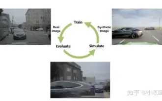 How to solve the long tail problem in autonomous driving scenarios?
Jun 02, 2024 pm 02:44 PM
How to solve the long tail problem in autonomous driving scenarios?
Jun 02, 2024 pm 02:44 PM
Yesterday during the interview, I was asked whether I had done any long-tail related questions, so I thought I would give a brief summary. The long-tail problem of autonomous driving refers to edge cases in autonomous vehicles, that is, possible scenarios with a low probability of occurrence. The perceived long-tail problem is one of the main reasons currently limiting the operational design domain of single-vehicle intelligent autonomous vehicles. The underlying architecture and most technical issues of autonomous driving have been solved, and the remaining 5% of long-tail problems have gradually become the key to restricting the development of autonomous driving. These problems include a variety of fragmented scenarios, extreme situations, and unpredictable human behavior. The "long tail" of edge scenarios in autonomous driving refers to edge cases in autonomous vehicles (AVs). Edge cases are possible scenarios with a low probability of occurrence. these rare events
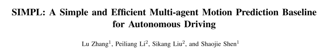 SIMPL: A simple and efficient multi-agent motion prediction benchmark for autonomous driving
Feb 20, 2024 am 11:48 AM
SIMPL: A simple and efficient multi-agent motion prediction benchmark for autonomous driving
Feb 20, 2024 am 11:48 AM
Original title: SIMPL: ASimpleandEfficientMulti-agentMotionPredictionBaselineforAutonomousDriving Paper link: https://arxiv.org/pdf/2402.02519.pdf Code link: https://github.com/HKUST-Aerial-Robotics/SIMPL Author unit: Hong Kong University of Science and Technology DJI Paper idea: This paper proposes a simple and efficient motion prediction baseline (SIMPL) for autonomous vehicles. Compared with traditional agent-cent
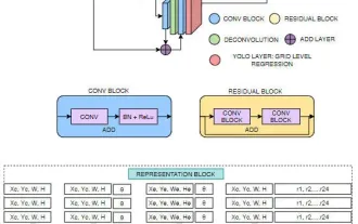 FisheyeDetNet: the first target detection algorithm based on fisheye camera
Apr 26, 2024 am 11:37 AM
FisheyeDetNet: the first target detection algorithm based on fisheye camera
Apr 26, 2024 am 11:37 AM
Target detection is a relatively mature problem in autonomous driving systems, among which pedestrian detection is one of the earliest algorithms to be deployed. Very comprehensive research has been carried out in most papers. However, distance perception using fisheye cameras for surround view is relatively less studied. Due to large radial distortion, standard bounding box representation is difficult to implement in fisheye cameras. To alleviate the above description, we explore extended bounding box, ellipse, and general polygon designs into polar/angular representations and define an instance segmentation mIOU metric to analyze these representations. The proposed model fisheyeDetNet with polygonal shape outperforms other models and simultaneously achieves 49.5% mAP on the Valeo fisheye camera dataset for autonomous driving
 This article is enough for you to read about autonomous driving and trajectory prediction!
Feb 28, 2024 pm 07:20 PM
This article is enough for you to read about autonomous driving and trajectory prediction!
Feb 28, 2024 pm 07:20 PM
Trajectory prediction plays an important role in autonomous driving. Autonomous driving trajectory prediction refers to predicting the future driving trajectory of the vehicle by analyzing various data during the vehicle's driving process. As the core module of autonomous driving, the quality of trajectory prediction is crucial to downstream planning control. The trajectory prediction task has a rich technology stack and requires familiarity with autonomous driving dynamic/static perception, high-precision maps, lane lines, neural network architecture (CNN&GNN&Transformer) skills, etc. It is very difficult to get started! Many fans hope to get started with trajectory prediction as soon as possible and avoid pitfalls. Today I will take stock of some common problems and introductory learning methods for trajectory prediction! Introductory related knowledge 1. Are the preview papers in order? A: Look at the survey first, p
 Let's talk about end-to-end and next-generation autonomous driving systems, as well as some misunderstandings about end-to-end autonomous driving?
Apr 15, 2024 pm 04:13 PM
Let's talk about end-to-end and next-generation autonomous driving systems, as well as some misunderstandings about end-to-end autonomous driving?
Apr 15, 2024 pm 04:13 PM
In the past month, due to some well-known reasons, I have had very intensive exchanges with various teachers and classmates in the industry. An inevitable topic in the exchange is naturally end-to-end and the popular Tesla FSDV12. I would like to take this opportunity to sort out some of my thoughts and opinions at this moment for your reference and discussion. How to define an end-to-end autonomous driving system, and what problems should be expected to be solved end-to-end? According to the most traditional definition, an end-to-end system refers to a system that inputs raw information from sensors and directly outputs variables of concern to the task. For example, in image recognition, CNN can be called end-to-end compared to the traditional feature extractor + classifier method. In autonomous driving tasks, input data from various sensors (camera/LiDAR
 Which version of Apple 16 system is the best?
Mar 08, 2024 pm 05:16 PM
Which version of Apple 16 system is the best?
Mar 08, 2024 pm 05:16 PM
The best version of the Apple 16 system is iOS16.1.4. The best version of the iOS16 system may vary from person to person. The additions and improvements in daily use experience have also been praised by many users. Which version of the Apple 16 system is the best? Answer: iOS16.1.4 The best version of the iOS 16 system may vary from person to person. According to public information, iOS16, launched in 2022, is considered a very stable and performant version, and users are quite satisfied with its overall experience. In addition, the addition of new features and improvements in daily use experience in iOS16 have also been well received by many users. Especially in terms of updated battery life, signal performance and heating control, user feedback has been relatively positive. However, considering iPhone14
